Helium leak test
Procedure AC3 · leak-test
Overview
A clamp-and-pump test that tells the clinician which side of a clamp a helium leak lies on by watching whether the balloon pressure waveform (BPW) baseline falls. It is the structured response to the three helium (HE) loss alarms once blood in the driveline has been ruled out, and it ends with the alarms re-enabled.
When to perform
Possible HE Loss 2, Possible HE Loss 3 or LARGE HE LEAK alarm with no blood in the driveline tubing; the helium tank losing pressure faster than expected; any other suspected helium leak.
Equipment
- rubber-shod hemostats
- spare IAB volume connector and driveline tubing of the same size (color)
Steps
Before anything else, inspect the intra-aortic balloon (IAB) catheter and driveline tubing for blood, including rust-colored flecks or coffee-ground material. If any is present, disconnect the IAB connector from the pump, clamp the tubing, DO NOT RESUME PUMPING, contact the physician and prepare for IAB removal (and a new IAB if support is still needed).1
Blood in the gas pathway means the balloon membrane has breached, and pumping helium into a ruptured balloon risks gas embolism; the leak test is only for the case where no blood is seen.
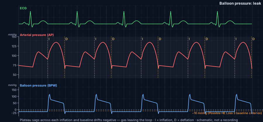
Leak pattern: the plateau and baseline sag beat by beat as helium escapes the closed loop; the −10 mmHg line is the Possible HE Loss criterion Gather rubber-shod hemostats plus a spare IAB volume connector and tubing.1
The test clamps the driveline, and the later steps may require cutting tubing and replacing the connector.
Press the alarm-silence corner switch or the touchscreen control to silence the audible alarms.2
The high-priority tone would otherwise continue while the clinician works through the test.
Press the Alarms tab, set the timer to 10 minutes, and press ALARMS OFF to disable the pneumatic alarms.2
Pumping against a clamp would repeatedly trip the pneumatic alarms and stop the pump; with those alarms suspended the pump keeps running and only displays messages.
Clamp the driveline tubing with the rubber-shod hemostats between the quick connect and the IAB bifurcation. Do NOT clamp the IAB catheter itself.2
The first clamp isolates the patient side (catheter and balloon) from the pump side; clamping the catheter can damage it and force replacement.
Press the ON control key to start pumping.2
Pumping against the clamp pressurizes only the pump-side pathway, so any fall in pressure must come from a leak on that side.
Observe the BPW. If the baseline falls, the leak is between the pump and the clamp. If the baseline does not fall, the leak is probably on the patient side: consider stopping the pump, removing the balloon catheter and inserting another.2
A steady baseline with the patient side clamped off means the pump-side pathway holds gas, so the loss must be beyond the clamp in the catheter or balloon.
If the leak was not placed on the patient side, press PUMP OFF and remove the hemostat.2
The manual gives no reason; the evident logic is that a pump-side fall must be localized further, so the clamp is moved closer to the console.
Move the hemostat to just above the IAB connector, close to the IABP console.2
The second clamp isolates everything except the console and the volume connector, so the leak can be narrowed to those two.
Press PUMP ON and observe the BPW baseline. If it falls, the leak is in the pump or at the IAB volume connector.2
With almost all external tubing clamped off, a falling baseline leaves only the console and the connector joint as the source.
Check the O-rings on the balloon connector, wipe away debris, ensure the quick-connect at the IAB bifurcation is tight, and examine the tubing at the balloon connector and catheter junction for stretching. Repair stretched tubing per the tubing repairs, and if O-rings are damaged or missing, replace the driveline tubing from the quick connect to the IAB volume connector with a connector of the same size (color).2
Worn O-rings and stretched tubing are the common external leak points; a different-color replacement connector would change the balloon volume the pump delivers.
Repeat the alarms-off, clamp and pump-on steps. If the baseline is now steady, the leak is corrected and pumping can resume. If it continues to fall, the leak is in the control system or the connector.2
Re-testing after the repair confirms whether the external fix removed the loss.
Press PUMP OFF and remove the hemostat.3
The pump must be off and the line unclamped before the connector is removed and the tubing cut.
Remove the balloon connector, cut off 1/2 inch of tubing, refit the connector, and repeat the alarms-off, clamp and pump-on steps. Steady baseline means corrected; a still-falling baseline means a possible internal console leak, so call Arrow® for service.3
Tubing stretched by the compression ring leaks at the connector; a fresh cut gives the connector an undamaged seal, and if that does not stop the fall the leak is inside the console.
If the alarms are still disabled, press the ON control key to re-enable them.3
The 10-minute timer expires on its own, but until it does the pump will not stop or print on a pneumatic alarm, leaving the patient unprotected.
Press ALARM RESET to remove the alarm messages.3
Clearing the stale messages restores normal alarm display for any new condition.
Cautions
- If blood is present in the IAB catheter or driveline, DO NOT RESUME PUMPING; contact the physician and prepare for IAB removal.1
- Do not clamp the IAB catheter itself; clamping it may damage the catheter and require replacement.2
- A replacement IAB volume connector must be the same size (color) so the delivered IAB volume stays the same.2
- Alarms should only be turned OFF when the pump is under constant observation by a trained clinician, and only for a brief period while correcting an alarm condition.4
- A Possible HE Loss 3 may be impaired helium movement (kink, high heart rate, timing) rather than a leak; placing the pump in 1:2 first shows whether the alarm persists.5
Related knowledge
- Possible HE Loss 2 (AL-012)
- Blood in the driveline on a helium-loss alarm (AL-013)
- Possible HE Loss 3 criteria (AL-014)
- Differentiating HE Loss 3 causes with 1:2 (AL-015)
- LARGE HE LEAK (AL-019)
- HE loss alarm: first check for blood (TS-010)
- Sorting the three HE loss alarms (TS-011)
- Leak test preparation (TS-012)
- First clamp position (TS-013)
- Reading the BPW with the driveline clamped (TS-014)
- Second clamp and the IAB volume connector (TS-015)
- Finishing the leak test (TS-016)
- Leak and baseline alarm thresholds on the BPW (TS-026)
- Leak pattern on the balloon pressure waveform (WV-008)
References
- Arrow International Inc. AC3™ Series IABP System Service Manual. Part No. IAM-9011, Rev 00. Reading, PA: Arrow International Inc (Teleflex); 2015. p 215.
- Arrow International Inc. AC3™ Series IABP System Service Manual. Part No. IAM-9011, Rev 00. Reading, PA: Arrow International Inc (Teleflex); 2015. p 218.
- Arrow International Inc. AC3™ Series IABP System Service Manual. Part No. IAM-9011, Rev 00. Reading, PA: Arrow International Inc (Teleflex); 2015. p 220.
- Arrow International Inc. AC3™ Series IABP System Service Manual. Part No. IAM-9011, Rev 00. Reading, PA: Arrow International Inc (Teleflex); 2015. p 181.
- Arrow International Inc. AC3™ Series IABP System Service Manual. Part No. IAM-9011, Rev 00. Reading, PA: Arrow International Inc (Teleflex); 2015. p 190.
- Arrow International Inc. AC3™ Series IABP System Service Manual. Part No. IAM-9011, Rev 00. Reading, PA: Arrow International Inc (Teleflex); 2015. p 165.
- Arrow International Inc. AC3™ Series IABP System Service Manual. Part No. IAM-9011, Rev 00. Reading, PA: Arrow International Inc (Teleflex); 2015. pp 180-181.
- Arrow International Inc. AC3™ Series IABP System Service Manual. Part No. IAM-9011, Rev 00. Reading, PA: Arrow International Inc (Teleflex); 2015. pp 189-193.
- Arrow International Inc. AC3™ Series IABP System Service Manual. Part No. IAM-9011, Rev 00. Reading, PA: Arrow International Inc (Teleflex); 2015. pp 215-221.